

|
My Talk on 29 Nov 2012 |
|
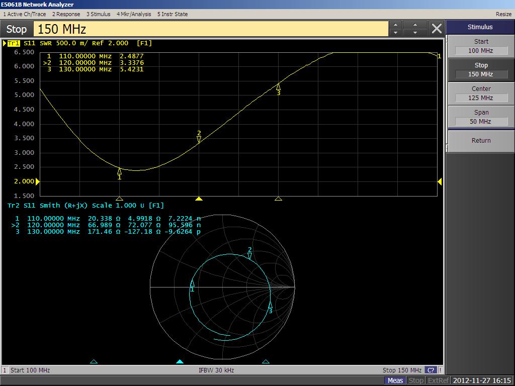
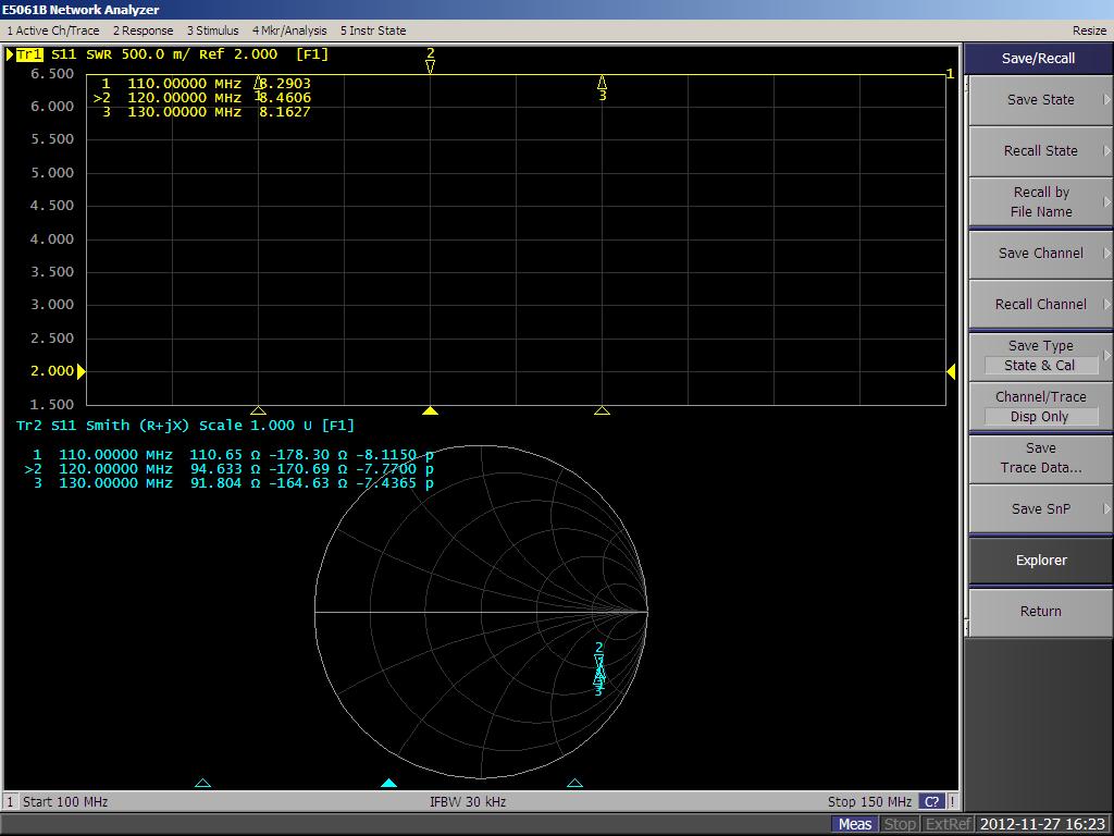
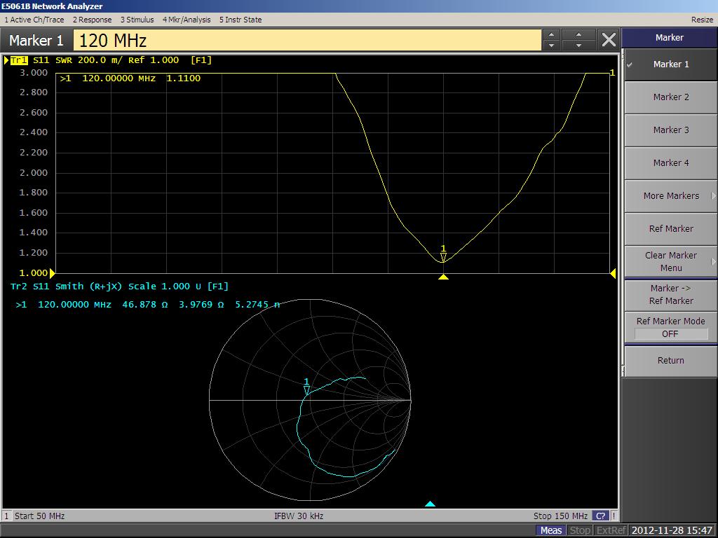
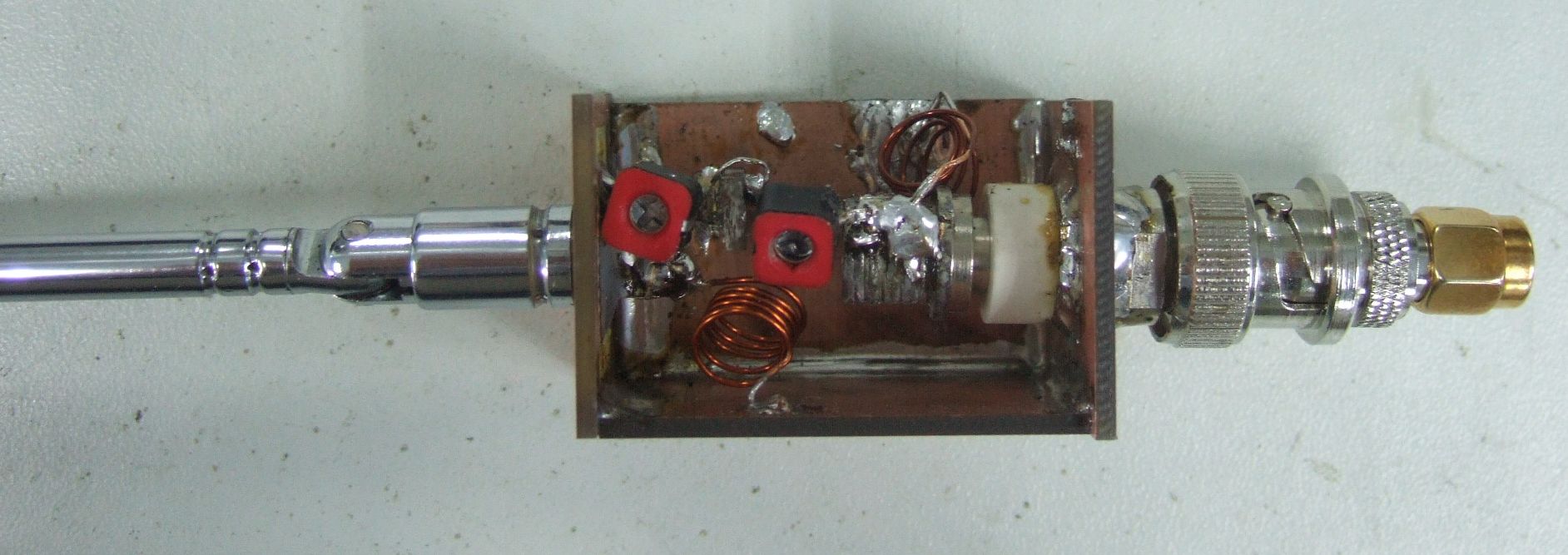
The last club meeting for the year is in November. It was decided long ago by the OMs that we should have a recess each December, because many members will be travelling at that time. The number of volunteers for talks had petered down somewhat, so I decided to “pow buay”. This is a Chinese term to mean literally “take the tail” viz volunteer your services when there are no more volunteers left. Min Than 9V1XY who had just obtained his callsign volunteered to help out during the talk, as well as after the talk (in the videos which I made). We also roped in another “aspiring lady ham” for the videos. I decided that after 10 months, the members would be tired to seeing Powerpoints (yes, I heard from a friend that there is an “ANTI-POWERPOINT” movement somewhere), so we decided that it would be a practical demo and whiteboard talk. DEMO 1: UHF Whip Lights Fluorescent Tube at the max voltage point It is quite common knowledge that in an antenna, the maximum voltage occurs at the point of minimum current. This is in order to satisfy the boundary conditions. The test setup was as follows: We built a simple whip antenna sitting on a double sided PCB, with the PCB acting as a ground plane. An old transistor radio whip was used. Please remember to grind off the copper where the antenna is attached. This ground plane was then mounted on 2 pieces of wood for mounting / stability purposes. We then attached the feedpoint to the network analyzer and extended the whip for lowest VSWR at 435MHz (that’s the frequency we will use). This antenna was then attached to my trusty old FT2700 with the dead VHF section (UHF is still working fine). Keying the radio at 25W will light up a fluorescent tube held at the tip of the antenna. Once the tube is fired up, you can slide it up and down to see the voltage vary. The video we made is here. DEMO 2: UHF Dipole receives RF energy from afar, enough to flip an analog meter This is another simple demo that came naturally through our experiments in building UHF dipoles. My ham buddy Giulio 9V1FC shares this same interest. We decided to experience for ourselves the delight of “action at a distance”. The test setup was as follows: Two similar UHF dipoles for 435MHz were built. One was driven by my FT2700 and the other was connected to an old Yokogawa 0.2mA FSD panel meter via a simple 1N5711 diode and some caps. Here is the video we made. LECTURE 1: How to build a “both-ways” matched whip antenna for a TSC100RA When we attach an antenna to a transceiver, we are usually more concerned with the antenna impedance when we TX. For that we are “quite sure” that the manufacturer made the output Z equal to 50 ohms. When we release the PTT button, we accept “on faith…. Haha” that the receive impedance is also 50 ohms and that our poor antenna will do its job well. I received a TSC100RA from a good friend recently. This is an air and marine band receiver. You see, on a receiver, because we don’t TX, we can explore further this input impedance matter! My first video shows the receiver attached to my Network Analyzer and how its input Z changes when we change band. The rasping sound you hear from the receiver is the sound of the analyzer’s scanning The following pictures are self explanatory. Enjoy the pics and your comments are welcome (via the feedback link at the top bar)/ Input Impedance of the receiver Unmatched whip at the feedpoint Input impedance after matching Completed antenna and matching circuit.
|